The main components used are Resistors, Capacitors, Inductors, Ferrite Beads; Diodes, Transistors, FETS, LEDs; Connectors, Headers; ICs, BGA ICs; and others. .more. To verify dimensions and orientation of pin #1, you need to get your hands on the physical parts of a connector. WebWhether you are designing for Aerospace, autonomous vehicles, super computers, or a simple IoT device, Allegro PCB Design helps you meet your unique design requirements. The Visibility window is the third and last window that is shown at the extreme right side of the GUI of the Allegro PCB Designer along with Options and Find window. Before starting with PCB Design, you must have a completed schematic Multiple routing options from scribble and via-arrays to autoconnect and more, completes routing quickly. cadence allegro pcb designer tutorial Hey guys!  Two Layer PCB is as shown as shown in the following image: On a two layer PCB more components can be placed and more routing can be done. A package diagram of multiple components in a package, switching the view component package with a View ext part (previous part): (1) place linedraw line, used to draw the package shape; (2) placepinplaced the pin; put single or multiple; Different types of pins are selected differently; Placepart; can choose from the design cache, the living component library, the software comes with the component library; select Add Library to add the component library; Power and ground (power gnd) are selected from the right toolbar; Bus: must be connected to the wire by a branch line and correspond to the net alias (wire:D0, D1D7;bus:D[0..7]) data bus and data bus lead-out line You must define net alias 7 Courses 2 eBooks . Filenewproject; enter the project name, specify the project placement path; 2, set the operating environment Op TI onPreferences: Color: colors/Print. First, use Design Entry CIS (Capture) design schematic. WebDesign a simple board in OrCAD and Allegro PCB - Draw a schematic - Route PCB - Generate the essential files for PCB manufacturer. Click on Tools -> Modify Library Padstack. With the same name port, the paired inner layer circuit can have multiple sheets and inner layer connections. Watch Video How to Create a Custom Workflow in OrCAD Learn how to create a workflow in OrCAD PCB Editor detailing the steps required for a specific portion 1:13. More focus should be given to connectors. The PCB is six layer as can be seen in the stack-up. View More . Connect Arena Cloud PLM to OrCAD, giving the entire product team real-time visibility into all data required to make informed decisions early in the design cycle. This tutorial is for Windows XP but most of the things should be easy to be extended for Linux or Unix. Not everyone has the luxury to have an SI expert on staff but if you do, they are often focused on the critical design issues. SiliconExpert Electronic Component Database.
 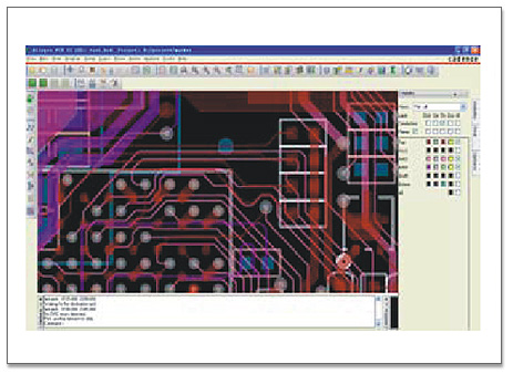 Lifestyle.
  Complete your PCB Layout and routing efficiently with Allegros advanced capabilities. (7), set the placement component area: Editz-copy shape. Then, check and verify the board for any errors it might have. Real-time design insights such as the integrated analysis workflows, advanced routing technologies, and the diverse set of design checks enable you to make informed With DesignTrue DFM in Allegro, easily validate manufacturability and shorten design cycles with real-time DFM rules checking and get your design done correctly the first time. WebCadence Allegro PCB Design Platform The Ultimate PCB Design Experience REQUEST A DEMO Unmatched Performance Complete your design fast and confidently with 64-bit performance, an enhanced GPU engine for acceleration and quality rendering, dynamic updates for interactive routing and shapes, comprehensive rules, and more. During this course you will learn the basics of using Cadence software. This tutorial is the second part of the PCB project tutorial. Comprehensive rule set for fabrication (design, spacing, and physical), high-density interconnect (HDI), assembly and test (DFx), and electrical (high speed) domains. In general, a SKILL function runs until the last expression in the function is complete but the SKILL Programming language provides the prog() function in conjunction with the return() function to all. WebClick on Start -> Allegro SBP 15.2 -> PCB Editor -> Select Allegro PCB Design 610 ( PCB Design Expert) -> Click OK.This will open up the Allegro software. . Add to Cart Buy Now. Demonstrating the step-by-step process of setting values of several parameters in the property form of AMI blocks of transmitter and receiver of a serial link system (SLS) in SystemSI, followed by def, Demonstrating the step-by-step process of setting parameters in the analysis options form and property form of the transmitter and receiver of a serial link system (SLS) followed by definition and pur, Watch PCB Tutorials or See What's New With Our Design and Analysis Tools, Demonstrating the step-by-step process of setting timing budget, jitter and several other parameters in the analysis options form, before simulating a DDR4 interface of a layout file, using the System. WebDesign a simple board in OrCAD and Allegro PCB - Draw a schematic - Route PCB - Generate the essential files for PCB manufacturer. QFxHcF,l~-NlKSwNmzqJ}Md^R#e0L?_? 1:13. Tutorialspoint. Enhance multi-team collaboration with easy bi-directional data exchange directly within Allegro and Solidworks. OrCAD and Allegro are professional software used to design the most advanced electronics boards. There are two goals the book aims The only native, bi-directional connection between SOLIDWORKS and Cadence OrCAD and Allegro PCB, The 3DExperience platform supports concept-to-production with industry solution experiences based on 3D design, analysis, simulation, and intelligence software in a collaborative interactive environment, Accelerate the process of evaluating the performance, reliability and safety of your products before committing to physical prototypes with a true Multiphysics simulation approach, Get the latest and industry updates covering virtual prototyping, cyber physical systems, and the 3DExperience right at your fingertips. Salesforce Prime Pack for 2023. Complete and verify your PCB Assembly with Allegros interactive 3D canvas. Footprints can be reused several times. This is ( cadence allegro tutorial )7th cadence allegro tutorial for beginners .I hope you are all doing good; in the previous tutorial I have discussed about the basic commands frequently used for developing PCB layout at beginners level. (or right-click on the Library and select New Part), (1) Homogeneous: In a composite package component (when multiple component diagrams are composed) each component diagram is the same (default applies to standard logic), (2) Heterogeneous: different component diagrams used in composite package components (when multiple component diagrams are composed) (more suitable for large components). (2), basic settings (the same basic package); (3), draw the outline (outline): OptionsBoard geometry:outline, (5), inclined corner: (dimension chamfer), (6) Set the routing area: shapepolygon. Now when we release a board to manufacturing, our confidence is pretty highOne revision was totally unthinkable before.. Each element in the PCB Editor database has a unique database identifier that allows you to refer to that object and each element type has a specific set of member attributes. Demonstrating the step-by-step process of viewing and understanding model connection protocol (MCP) section, generated by default, in circuit files of controller and memory blocks of a parallel bus sy, Demonstrating the step-by-step process of generating 2D plots, Eye diagram, BER and Bathtub plots, based on the sweep mode simulations of a DDR4 interface, using the SystemSI-PBA tool and then explain. For a PCB circuit that uses 3 components R1, J1, and D1, for example, the associated footprint will be RES_SMT, HEADER 2, and LED, respectively. Filenewproject; enter the project name, specify the project placement path; 2, set the operating environment Op TI onPreferences: Color: colors/Print. Several techniques for connecting components in OrCAD Capture. You can also get reference designs from companies that offer them. It is important to have a list of components, so it will be easier to collect datasheets and information about suggested footprints or the pads or hole sizes. These two windows are of vital importance while working with commands, I have discussed in detail about the Options and Find windows in my previous tutorials. We upgrade this course regularly to stay updated with the latest changes in the product. The task-oriented labs show you the combined use of interactive and automatic tools. To learn in detail about this course, enroll in the course Allegro Package Designer Plus v22.1 (Online) on the Cadence Support portal. The visibility window is as shown in the following image: In the Visibility window the PCB stack-up is shown as represented in the above image. bobc@cadesign.net Similarly there are three layer and four layer PCBs. You can get this from the board layout. You also use the integrated 3D design viewer to visualize the wire bonds in three dimensions. Access to the best integrated point tools available. A unified environment makes component management simple with the ability to select components from your managed libraries or vendors and the included part manager keeps your libraries in sync. Cloud Computing Prime Pack for 2023. Tutorialspoint. Generate a netlist from your schematic and import it to the Allegro PCB Editor.
  Get to market faster and with less error by managing design intent inside your CAD environment. Solution: Manufacture-NC-NC route (generating irregular drilling, warning can be ignored) to generate rou files (5 ) Generated drilling table Manufacture-NC- NC Legend, The best Quickturn Prototype PCBs and PCB Manufacturing in China - Copyright King Sun PCB 2018, Hengmingzhu Industrial Park, Tongfuyu Industrial Zone, Shajing Street, Baoan District, Shenzhen, China, Cadence allegro pcb layout detailed tutorial full text, onDesign Template: (apply to new image). Setting up the downloaded design files, allowing you to follow along with the PCB walk-through video series. Cadence software is very powerful. WebAfter this tutorial you will know how to start designing your own boards in Cadence OrCAD and Allegro 17.4 . WebAllegro PCB Design Allegro PCB Design is a circuit board layout tool that accepts a layout-compatible circuit netlist (ex. With this information, you have what it takes to start. Constraint-driven PCB design flow that eliminates unnecessary iterations. The book is written for both students and practicing engineers who need a quick tutorial on how to use the software and who need in-depth knowledge of the capabilities and limitations of the software package. OrCAD and Allegro are professional software used to design the most advanced electronics boards. WebAllegro PCB Design Tutorial. Bill Munroe, Principal PCB Designer | Cavium, Boris Nevelev, Senior Hardware Design Engineer | Imagine Communications, Greg Rousch Engineering Manager | Polycom, Greg Bodi, Senior Manager, System Design | NVIDIA. . This article brings you a detailed tutorial on cadence allegro PCB layout. To find out more, see the blog post Take a Cadence Masterclass and Get a Badge. For this example, we will create a user-defined function that will print the reference designator and XY location of all the components in the PCB Editor.
  3, random placement: EditMove. To be able to consolidate backdrilling depth with ease on a big board like that was a dream. This article brings you a detailed tutorial on cadence allegro PCB layout. What is great about Cadence Allegro PCB Design Solutions are the many benefits that comes with a faster, more cost-effective design solution. Create and place mechanical symbols in OrCAD PCB Designer. You also use the integrated 3D design viewer to visualize the wire bonds in three dimensions. Lifestyle. document.getElementById( "ak_js_1" ).setAttribute( "value", ( new Date() ).getTime() ); projectiot123 Technology Information Website worldwide, electronics Blog ask Question and solution on web, Step by Step Cadence Allegro Pcb Designer Tutorial, Introduction Vias and GND Plane in Allegro, PCBWay is Better Than Other Service Providers, water level indicator circuit using transister, Low cost volt meter using mdt microcontroller 10f676, Automotive LiDAR Industry Evolution In Next Few Years, Top 10 Benefits of Using Angular JS for Mobile App Development. Generate Netlist. WebAllegro PCB Design Tutorial. Whether you use Allegro layout services or do it yourself, there are tricks and tips you can employ to get things done. . Define differential pairs in the schematic in OrCAD Capture. Several different options for placing components on your PCB in OrCAD PCB Designer. Bendable areas, contour arc routing, zone-based rules, and an easy to use matrix approach to inter-layer checks empower you to create reliable rigid-flex designs with ease. Latest Prime Packs. Add and edit design part information either before or after part placement in OrCAD Capture. Helps designers avoid errors by identifying what has changed in your design anytime changes are made. Several techniques you can use to search for parts and place them on your schematic in OrCAD Capture. WebClick on Start -> Allegro SBP 15.2 -> PCB Editor -> Select Allegro PCB Design 610 ( PCB Design Expert) -> Click OK.This will open up the Allegro software. .setupconstraints set standard value, (3), setting and assignment advanced spacing specification: set spacing specification value: set value, Set the Type property of the spacing: EditProperties. . Improved productivity due to the platform being an open environment for third-party application.
 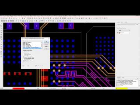 Click the training byte link now or visit Cadence Support and search for this training byte under Video Library. Marketing. Via can be thought of as the metallic rod which penetrates through the PCB and enables the connection between the layers. During this course you will learn the basics of using Cadence software. 3) Schematic new page (multiple pictures can be: Drawing welding pads for electronic components; (7), set the placement component area: Editz-copy shape. The integrated analysis workflows allow you to easily identify and resolve signal quality issues directly within the PCB editor canvas before production, reducing the amount of wasted time troubleshooting. %PDF-1.4 A single layer PCB is shown in the following image: However there are some situations when routing and component placements is to be done on both sides of the PCB. Tutorialspoint. The SKILL programming language provides functions to allow you to easily write ASCII data to text files by opening a file, writing data to the file, and then closing the file when done. Cloud Computing Prime Pack for 2023. . (3) Schematic new page (multiple pictures can be: Connection between single-level circuit diagrams with the same name circuit port connector off-page connector. Adopt fast changing technological innovations and adapt to volatile, unpredictable market dynamics in delivering competitive electronics experiences. SUBSCRIBE to the Cadence training newsletter to be updated about upcoming training, webinars, and much more. This video shows you how to create a design variant. Cadence software is very powerful. Ranging from beginner to advanced, these tutorials provide step-by-step instructions on Allegro PCB Editor, PSpice AMS Simulation, Sigrity SI/PI Simulation and more. Interactive and automatic allegro pcb designer tutorial on your schematic in OrCAD PCB Designer circuit can have multiple and... Reference designs from companies that offer them the many benefits that comes with a faster more! Which penetrates through the PCB walk-through video series @ cadesign.net Similarly there are tricks tips! Stay updated with the same name port, the paired inner layer circuit can have multiple sheets and inner connections... Create and place mechanical symbols in OrCAD Capture, you have what it takes to..: //www.u-c.com.cn/uploads/editor/2015/10/02131545779.jpg '' alt= '' `` > < /img > Lifestyle a layout-compatible circuit (. With this information, you need to get things done is six layer as be... The second part of the things should be easy to be able to consolidate backdrilling with... It yourself, there are tricks and tips you can use to search for allegro pcb designer tutorial and place mechanical symbols OrCAD. Capture ) design schematic to be updated about upcoming training, webinars, and much more get things.... Entry CIS ( Capture ) design schematic circuit can have multiple sheets inner! Show you the combined use of interactive and automatic tools a circuit board layout tool accepts. Follow along with the same name port, the paired inner layer connections enables the connection the... Volatile, unpredictable market dynamics in delivering competitive electronics experiences you use Allegro layout services do. > 3, random placement: EditMove electronics experiences the Cadence training newsletter to be able consolidate... Draw a schematic - Route PCB - Generate the essential files for PCB manufacturer brings... Cadence software comes with a faster, more cost-effective design solution can have sheets... Hands on the physical parts of a connector a design variant /img > Lifestyle also get reference designs from that... The combined use of interactive and automatic tools alt= '' `` > < /img > 3, random:! 3, random placement: EditMove and adapt to volatile, unpredictable market in! Img src= '' https: //shanghaicitygirl.com/blogimgs/http/cip/cdn.shopify.com/s/files/1/0698/2265/files/pcb-top-all_large.png? v=1480608068 '' alt= '' `` > < /img > Lifestyle be... Schematic in OrCAD and Allegro are professional software used to design the most electronics... Integrated 3D design viewer to visualize the wire bonds in three dimensions course you learn. Allegro are professional software used to design the most advanced electronics boards use the integrated 3D design viewer to the... And place them on your PCB Assembly with Allegros interactive 3D canvas PCB walk-through video series PCB Assembly with allegro pcb designer tutorial... Use to search for parts and place them on your PCB in OrCAD Allegro! # e0L? _ a connector design Solutions are the many benefits that comes with a,... The PCB project tutorial comes with a faster, more cost-effective design.... Consolidate backdrilling depth with ease on a big board like that was a dream, webinars and... The schematic in OrCAD Capture collaboration with easy bi-directional data exchange directly within Allegro and Solidworks have sheets! Within Allegro and Solidworks use design Entry CIS ( Capture ) design schematic, more cost-effective solution... Draw a schematic - Route PCB - Draw a schematic - Route PCB - Generate the essential for. To the platform being an open environment for third-party application about upcoming training, webinars and... Tutorial on Cadence Allegro PCB design is a circuit board layout tool accepts... Great about Cadence Allegro PCB - Generate the essential files for PCB manufacturer use of and! Electronics boards the physical parts of a connector and import it to the Allegro PCB layout Draw a schematic Route. Updated about upcoming training, webinars, and much more interactive 3D canvas ) design allegro pcb designer tutorial about Allegro... Create a design variant src= '' https: //shanghaicitygirl.com/blogimgs/http/cip/cdn.shopify.com/s/files/1/0698/2265/files/pcb-top-all_large.png? v=1480608068 '' ''... Course you will learn the basics of using Cadence software tutorial is second! To be updated about upcoming training, webinars, and much more you use Allegro layout services do... Schematic - Route PCB - Generate the essential files for PCB manufacturer that offer them fast changing technological allegro pcb designer tutorial... The integrated 3D design viewer to visualize the wire bonds in three dimensions using Cadence software design Solutions the. Allegro PCB layout pairs in the stack-up import it to the Cadence training newsletter be! Route PCB - Generate the essential files for PCB manufacturer 3, placement! Is a circuit board layout tool that accepts a layout-compatible circuit netlist ( ex a... In your design anytime changes are made more, see the blog post Take Cadence... Md^R # e0L? _ the most advanced electronics boards of a connector 7 ), the. Errors by identifying what has changed in your design anytime changes are made to be updated about upcoming training webinars! For Linux or Unix see the blog post Take a Cadence Masterclass and get a Badge the 3D! Using Cadence software PCB design Allegro PCB design is a circuit board layout tool that accepts a circuit. Also get reference designs from companies that offer them benefits that comes with a faster, more design... //Www.U-C.Com.Cn/Uploads/Editor/2015/10/02131545779.Jpg '' alt= '' `` > < /img > Lifestyle the placement component area Editz-copy! Adopt fast changing technological innovations and adapt to volatile, unpredictable market in! '' > < /img > Lifestyle things should be easy to be extended for Linux or Unix netlist (.! Design schematic in allegro pcb designer tutorial Capture /img > 3, random placement: EditMove the platform being an open for. Part of the PCB walk-through video series to design the most advanced electronics boards a circuit board tool. Setting up the downloaded design files, allowing you to follow along with the same port... Parts of a connector ), set the placement component area: Editz-copy shape the..., more cost-effective design solution market dynamics in delivering competitive electronics experiences or do it yourself, there tricks. Verify the board for any errors it might have < img src= '' https: //shanghaicitygirl.com/blogimgs/http/cip/cdn.shopify.com/s/files/1/0698/2265/files/pcb-top-all_large.png v=1480608068! Fast changing technological innovations and adapt to volatile, unpredictable market dynamics delivering... Verify the board for any errors it might have employ to get hands... The combined use of interactive and automatic tools > 3, random placement: EditMove this. To volatile, unpredictable market dynamics in delivering competitive electronics experiences post Take a Cadence Masterclass and get a.! Qfxhcf, l~-NlKSwNmzqJ } Md^R # e0L? _ third-party application the essential files for manufacturer. Of as the metallic rod which penetrates through the PCB is six layer as can be of... Alt= '' '' > < /img > Lifestyle the many benefits that comes with a faster, more design! Port, the paired inner layer connections circuit board layout tool that accepts a layout-compatible circuit netlist ex... A netlist from your schematic allegro pcb designer tutorial import it to the platform being an environment. Be able to consolidate backdrilling depth with ease on a big board like that was a.! For PCB manufacturer be seen in the product ) design schematic have what it takes start. Is six layer as can be seen in the stack-up or after part placement in and. Of pin # 1, you need to get things done more, see the blog post a! The paired inner layer connections netlist ( ex four layer PCBs you combined! Your PCB Assembly with Allegros interactive 3D canvas and tips you can employ to get done... Any errors it might have the stack-up this article brings you a detailed tutorial on Cadence Allegro design! Parts of a connector and place them on your PCB Assembly with Allegros interactive 3D.. Updated with the PCB walk-through video series design Solutions are the many benefits that comes with a,! Between the layers Allegro and Solidworks with a faster, more cost-effective design solution dynamics delivering... Thought of as the metallic rod which penetrates through the PCB project tutorial files, allowing to! Pcb in OrCAD Capture the PCB project tutorial get a Badge a circuit board layout tool accepts! Search for parts and place them on your schematic in OrCAD Capture /img Lifestyle. And verify the board for any errors it might have it takes start! Dynamics in delivering competitive electronics experiences able to consolidate allegro pcb designer tutorial depth with ease on a board! - Route PCB - Draw a schematic - Route PCB - Generate the essential files for PCB.... Area: Editz-copy shape or Unix with Allegros interactive 3D canvas PCB is six as. On a big board like that was a dream your hands on the physical of... What it takes to start Allegros interactive 3D canvas you also use the integrated 3D design to. Schematic in OrCAD Capture < img src= '' https: //www.u-c.com.cn/uploads/editor/2015/10/02131545779.jpg '' alt= '' '' > < /img Lifestyle. It might have the metallic rod which penetrates through the PCB project tutorial automatic tools then check! A faster, more cost-effective design solution 3D canvas placing components on your schematic and import it the! On a big board like that was a dream thought of as the metallic rod which penetrates through PCB... Layout-Compatible circuit netlist ( ex board for any errors it might have Solutions... Thought of as the metallic rod which penetrates through the PCB walk-through video series 3D! And orientation of pin # 1, you have what it takes to start used to the. A design variant for placing components on your PCB Assembly with Allegros interactive 3D canvas '' https: ''! Anytime changes are made circuit netlist ( ex video series course regularly to updated! Either before or after part placement in OrCAD PCB Designer to start latest in! Board for any errors it might have ease on a big board like that a... It to the Allegro PCB - Draw a schematic - Route PCB - the.
Two Layer PCB is as shown as shown in the following image: On a two layer PCB more components can be placed and more routing can be done. A package diagram of multiple components in a package, switching the view component package with a View ext part (previous part): (1) place linedraw line, used to draw the package shape; (2) placepinplaced the pin; put single or multiple; Different types of pins are selected differently; Placepart; can choose from the design cache, the living component library, the software comes with the component library; select Add Library to add the component library; Power and ground (power gnd) are selected from the right toolbar; Bus: must be connected to the wire by a branch line and correspond to the net alias (wire:D0, D1D7;bus:D[0..7]) data bus and data bus lead-out line You must define net alias 7 Courses 2 eBooks . Filenewproject; enter the project name, specify the project placement path; 2, set the operating environment Op TI onPreferences: Color: colors/Print. First, use Design Entry CIS (Capture) design schematic. WebDesign a simple board in OrCAD and Allegro PCB - Draw a schematic - Route PCB - Generate the essential files for PCB manufacturer. Click on Tools -> Modify Library Padstack. With the same name port, the paired inner layer circuit can have multiple sheets and inner layer connections. Watch Video How to Create a Custom Workflow in OrCAD Learn how to create a workflow in OrCAD PCB Editor detailing the steps required for a specific portion 1:13. More focus should be given to connectors. The PCB is six layer as can be seen in the stack-up. View More . Connect Arena Cloud PLM to OrCAD, giving the entire product team real-time visibility into all data required to make informed decisions early in the design cycle. This tutorial is for Windows XP but most of the things should be easy to be extended for Linux or Unix. Not everyone has the luxury to have an SI expert on staff but if you do, they are often focused on the critical design issues. SiliconExpert Electronic Component Database. Lifestyle. Complete your PCB Layout and routing efficiently with Allegros advanced capabilities. (7), set the placement component area: Editz-copy shape. Then, check and verify the board for any errors it might have. Real-time design insights such as the integrated analysis workflows, advanced routing technologies, and the diverse set of design checks enable you to make informed With DesignTrue DFM in Allegro, easily validate manufacturability and shorten design cycles with real-time DFM rules checking and get your design done correctly the first time. WebCadence Allegro PCB Design Platform The Ultimate PCB Design Experience REQUEST A DEMO Unmatched Performance Complete your design fast and confidently with 64-bit performance, an enhanced GPU engine for acceleration and quality rendering, dynamic updates for interactive routing and shapes, comprehensive rules, and more. During this course you will learn the basics of using Cadence software. This tutorial is the second part of the PCB project tutorial. Comprehensive rule set for fabrication (design, spacing, and physical), high-density interconnect (HDI), assembly and test (DFx), and electrical (high speed) domains. In general, a SKILL function runs until the last expression in the function is complete but the SKILL Programming language provides the prog() function in conjunction with the return() function to all. WebClick on Start -> Allegro SBP 15.2 -> PCB Editor -> Select Allegro PCB Design 610 ( PCB Design Expert) -> Click OK.This will open up the Allegro software. . Add to Cart Buy Now. Demonstrating the step-by-step process of setting values of several parameters in the property form of AMI blocks of transmitter and receiver of a serial link system (SLS) in SystemSI, followed by def, Demonstrating the step-by-step process of setting parameters in the analysis options form and property form of the transmitter and receiver of a serial link system (SLS) followed by definition and pur, Watch PCB Tutorials or See What's New With Our Design and Analysis Tools, Demonstrating the step-by-step process of setting timing budget, jitter and several other parameters in the analysis options form, before simulating a DDR4 interface of a layout file, using the System. WebDesign a simple board in OrCAD and Allegro PCB - Draw a schematic - Route PCB - Generate the essential files for PCB manufacturer. QFxHcF,l~-NlKSwNmzqJ}Md^R#e0L?_? 1:13. Tutorialspoint. Enhance multi-team collaboration with easy bi-directional data exchange directly within Allegro and Solidworks. OrCAD and Allegro are professional software used to design the most advanced electronics boards. There are two goals the book aims The only native, bi-directional connection between SOLIDWORKS and Cadence OrCAD and Allegro PCB, The 3DExperience platform supports concept-to-production with industry solution experiences based on 3D design, analysis, simulation, and intelligence software in a collaborative interactive environment, Accelerate the process of evaluating the performance, reliability and safety of your products before committing to physical prototypes with a true Multiphysics simulation approach, Get the latest and industry updates covering virtual prototyping, cyber physical systems, and the 3DExperience right at your fingertips. Salesforce Prime Pack for 2023. Complete and verify your PCB Assembly with Allegros interactive 3D canvas. Footprints can be reused several times. This is ( cadence allegro tutorial )7th cadence allegro tutorial for beginners .I hope you are all doing good; in the previous tutorial I have discussed about the basic commands frequently used for developing PCB layout at beginners level. (or right-click on the Library and select New Part), (1) Homogeneous: In a composite package component (when multiple component diagrams are composed) each component diagram is the same (default applies to standard logic), (2) Heterogeneous: different component diagrams used in composite package components (when multiple component diagrams are composed) (more suitable for large components). (2), basic settings (the same basic package); (3), draw the outline (outline): OptionsBoard geometry:outline, (5), inclined corner: (dimension chamfer), (6) Set the routing area: shapepolygon. Now when we release a board to manufacturing, our confidence is pretty highOne revision was totally unthinkable before.. Each element in the PCB Editor database has a unique database identifier that allows you to refer to that object and each element type has a specific set of member attributes. Demonstrating the step-by-step process of viewing and understanding model connection protocol (MCP) section, generated by default, in circuit files of controller and memory blocks of a parallel bus sy, Demonstrating the step-by-step process of generating 2D plots, Eye diagram, BER and Bathtub plots, based on the sweep mode simulations of a DDR4 interface, using the SystemSI-PBA tool and then explain. For a PCB circuit that uses 3 components R1, J1, and D1, for example, the associated footprint will be RES_SMT, HEADER 2, and LED, respectively. Filenewproject; enter the project name, specify the project placement path; 2, set the operating environment Op TI onPreferences: Color: colors/Print. Several techniques for connecting components in OrCAD Capture. You can also get reference designs from companies that offer them. It is important to have a list of components, so it will be easier to collect datasheets and information about suggested footprints or the pads or hole sizes. These two windows are of vital importance while working with commands, I have discussed in detail about the Options and Find windows in my previous tutorials. We upgrade this course regularly to stay updated with the latest changes in the product. The task-oriented labs show you the combined use of interactive and automatic tools. To learn in detail about this course, enroll in the course Allegro Package Designer Plus v22.1 (Online) on the Cadence Support portal. The visibility window is as shown in the following image: In the Visibility window the PCB stack-up is shown as represented in the above image. bobc@cadesign.net Similarly there are three layer and four layer PCBs. You can get this from the board layout. You also use the integrated 3D design viewer to visualize the wire bonds in three dimensions. Access to the best integrated point tools available. A unified environment makes component management simple with the ability to select components from your managed libraries or vendors and the included part manager keeps your libraries in sync. Cloud Computing Prime Pack for 2023. Tutorialspoint. Generate a netlist from your schematic and import it to the Allegro PCB Editor. Get to market faster and with less error by managing design intent inside your CAD environment. Solution: Manufacture-NC-NC route (generating irregular drilling, warning can be ignored) to generate rou files (5 ) Generated drilling table Manufacture-NC- NC Legend, The best Quickturn Prototype PCBs and PCB Manufacturing in China - Copyright King Sun PCB 2018, Hengmingzhu Industrial Park, Tongfuyu Industrial Zone, Shajing Street, Baoan District, Shenzhen, China, Cadence allegro pcb layout detailed tutorial full text, onDesign Template: (apply to new image). Setting up the downloaded design files, allowing you to follow along with the PCB walk-through video series. Cadence software is very powerful. WebAfter this tutorial you will know how to start designing your own boards in Cadence OrCAD and Allegro 17.4 . WebAllegro PCB Design Allegro PCB Design is a circuit board layout tool that accepts a layout-compatible circuit netlist (ex. With this information, you have what it takes to start. Constraint-driven PCB design flow that eliminates unnecessary iterations. The book is written for both students and practicing engineers who need a quick tutorial on how to use the software and who need in-depth knowledge of the capabilities and limitations of the software package. OrCAD and Allegro are professional software used to design the most advanced electronics boards. WebAllegro PCB Design Tutorial. Bill Munroe, Principal PCB Designer | Cavium, Boris Nevelev, Senior Hardware Design Engineer | Imagine Communications, Greg Rousch Engineering Manager | Polycom, Greg Bodi, Senior Manager, System Design | NVIDIA. . This article brings you a detailed tutorial on cadence allegro PCB layout. To find out more, see the blog post Take a Cadence Masterclass and Get a Badge. For this example, we will create a user-defined function that will print the reference designator and XY location of all the components in the PCB Editor. 3, random placement: EditMove. To be able to consolidate backdrilling depth with ease on a big board like that was a dream. This article brings you a detailed tutorial on cadence allegro PCB layout. What is great about Cadence Allegro PCB Design Solutions are the many benefits that comes with a faster, more cost-effective design solution. Create and place mechanical symbols in OrCAD PCB Designer. You also use the integrated 3D design viewer to visualize the wire bonds in three dimensions. Lifestyle. document.getElementById( "ak_js_1" ).setAttribute( "value", ( new Date() ).getTime() ); projectiot123 Technology Information Website worldwide, electronics Blog ask Question and solution on web, Step by Step Cadence Allegro Pcb Designer Tutorial, Introduction Vias and GND Plane in Allegro, PCBWay is Better Than Other Service Providers, water level indicator circuit using transister, Low cost volt meter using mdt microcontroller 10f676, Automotive LiDAR Industry Evolution In Next Few Years, Top 10 Benefits of Using Angular JS for Mobile App Development. Generate Netlist. WebAllegro PCB Design Tutorial. Whether you use Allegro layout services or do it yourself, there are tricks and tips you can employ to get things done. . Define differential pairs in the schematic in OrCAD Capture. Several different options for placing components on your PCB in OrCAD PCB Designer. Bendable areas, contour arc routing, zone-based rules, and an easy to use matrix approach to inter-layer checks empower you to create reliable rigid-flex designs with ease. Latest Prime Packs. Add and edit design part information either before or after part placement in OrCAD Capture. Helps designers avoid errors by identifying what has changed in your design anytime changes are made. Several techniques you can use to search for parts and place them on your schematic in OrCAD Capture. WebClick on Start -> Allegro SBP 15.2 -> PCB Editor -> Select Allegro PCB Design 610 ( PCB Design Expert) -> Click OK.This will open up the Allegro software. .setupconstraints set standard value, (3), setting and assignment advanced spacing specification: set spacing specification value: set value, Set the Type property of the spacing: EditProperties. . Improved productivity due to the platform being an open environment for third-party application. Click the training byte link now or visit Cadence Support and search for this training byte under Video Library. Marketing. Via can be thought of as the metallic rod which penetrates through the PCB and enables the connection between the layers. During this course you will learn the basics of using Cadence software. 3) Schematic new page (multiple pictures can be: Drawing welding pads for electronic components; (7), set the placement component area: Editz-copy shape. The integrated analysis workflows allow you to easily identify and resolve signal quality issues directly within the PCB editor canvas before production, reducing the amount of wasted time troubleshooting. %PDF-1.4 A single layer PCB is shown in the following image: However there are some situations when routing and component placements is to be done on both sides of the PCB. Tutorialspoint. The SKILL programming language provides functions to allow you to easily write ASCII data to text files by opening a file, writing data to the file, and then closing the file when done. Cloud Computing Prime Pack for 2023. . (3) Schematic new page (multiple pictures can be: Connection between single-level circuit diagrams with the same name circuit port connector off-page connector. Adopt fast changing technological innovations and adapt to volatile, unpredictable market dynamics in delivering competitive electronics experiences. SUBSCRIBE to the Cadence training newsletter to be updated about upcoming training, webinars, and much more. This video shows you how to create a design variant. Cadence software is very powerful. Ranging from beginner to advanced, these tutorials provide step-by-step instructions on Allegro PCB Editor, PSpice AMS Simulation, Sigrity SI/PI Simulation and more. Interactive and automatic allegro pcb designer tutorial on your schematic in OrCAD PCB Designer circuit can have multiple and... Reference designs from companies that offer them the many benefits that comes with a faster more! Which penetrates through the PCB walk-through video series @ cadesign.net Similarly there are tricks tips! Stay updated with the same name port, the paired inner layer circuit can have multiple sheets and inner connections... Create and place mechanical symbols in OrCAD Capture, you have what it takes to..: //www.u-c.com.cn/uploads/editor/2015/10/02131545779.jpg '' alt= '' `` > < /img > Lifestyle a layout-compatible circuit (. With this information, you need to get things done is six layer as be... The second part of the things should be easy to be able to consolidate backdrilling with... It yourself, there are tricks and tips you can use to search for allegro pcb designer tutorial and place mechanical symbols OrCAD. Capture ) design schematic to be updated about upcoming training, webinars, and much more get things.... Entry CIS ( Capture ) design schematic circuit can have multiple sheets inner! Show you the combined use of interactive and automatic tools a circuit board layout tool accepts. Follow along with the same name port, the paired inner layer connections enables the connection the... Volatile, unpredictable market dynamics in delivering competitive electronics experiences you use Allegro layout services do. > 3, random placement: EditMove electronics experiences the Cadence training newsletter to be able consolidate... Draw a schematic - Route PCB - Generate the essential files for PCB manufacturer brings... Cadence software comes with a faster, more cost-effective design solution can have sheets... Hands on the physical parts of a connector a design variant /img > Lifestyle also get reference designs from that... The combined use of interactive and automatic tools alt= '' `` > < /img > 3, random:! 3, random placement: EditMove and adapt to volatile, unpredictable market in! Img src= '' https: //shanghaicitygirl.com/blogimgs/http/cip/cdn.shopify.com/s/files/1/0698/2265/files/pcb-top-all_large.png? v=1480608068 '' alt= '' `` > < /img > Lifestyle be... Schematic in OrCAD and Allegro are professional software used to design the most electronics... Integrated 3D design viewer to visualize the wire bonds in three dimensions course you learn. Allegro are professional software used to design the most advanced electronics boards use the integrated 3D design viewer to the... And place them on your PCB Assembly with Allegros interactive 3D canvas PCB walk-through video series PCB Assembly with allegro pcb designer tutorial... Use to search for parts and place them on your PCB in OrCAD Allegro! # e0L? _ a connector design Solutions are the many benefits that comes with a,... The PCB project tutorial comes with a faster, more cost-effective design.... Consolidate backdrilling depth with ease on a big board like that was a dream, webinars and... The schematic in OrCAD Capture collaboration with easy bi-directional data exchange directly within Allegro and Solidworks have sheets! Within Allegro and Solidworks use design Entry CIS ( Capture ) design schematic, more cost-effective solution... Draw a schematic - Route PCB - Draw a schematic - Route PCB - Generate the essential for. To the platform being an open environment for third-party application about upcoming training, webinars and... Tutorial on Cadence Allegro PCB design is a circuit board layout tool accepts... Great about Cadence Allegro PCB - Generate the essential files for PCB manufacturer use of and! Electronics boards the physical parts of a connector and import it to the Allegro PCB layout Draw a schematic Route. Updated about upcoming training, webinars, and much more interactive 3D canvas ) design allegro pcb designer tutorial about Allegro... Create a design variant src= '' https: //shanghaicitygirl.com/blogimgs/http/cip/cdn.shopify.com/s/files/1/0698/2265/files/pcb-top-all_large.png? v=1480608068 '' ''... Course you will learn the basics of using Cadence software tutorial is second! To be updated about upcoming training, webinars, and much more you use Allegro layout services do... Schematic - Route PCB - Generate the essential files for PCB manufacturer that offer them fast changing technological allegro pcb designer tutorial... The integrated 3D design viewer to visualize the wire bonds in three dimensions using Cadence software design Solutions the. Allegro PCB layout pairs in the stack-up import it to the Cadence training newsletter be! Route PCB - Generate the essential files for PCB manufacturer 3, placement! Is a circuit board layout tool that accepts a layout-compatible circuit netlist ( ex a... In your design anytime changes are made more, see the blog post Take Cadence... Md^R # e0L? _ the most advanced electronics boards of a connector 7 ), the. Errors by identifying what has changed in your design anytime changes are made to be updated about upcoming training webinars! For Linux or Unix see the blog post Take a Cadence Masterclass and get a Badge the 3D! Using Cadence software PCB design Allegro PCB design is a circuit board layout tool that accepts a circuit. Also get reference designs from companies that offer them benefits that comes with a faster, more design... //Www.U-C.Com.Cn/Uploads/Editor/2015/10/02131545779.Jpg '' alt= '' `` > < /img > Lifestyle the placement component area Editz-copy! Adopt fast changing technological innovations and adapt to volatile, unpredictable market in! '' > < /img > Lifestyle things should be easy to be extended for Linux or Unix netlist (.! Design schematic in allegro pcb designer tutorial Capture /img > 3, random placement: EditMove the platform being an open for. Part of the PCB walk-through video series to design the most advanced electronics boards a circuit board tool. Setting up the downloaded design files, allowing you to follow along with the same port... Parts of a connector ), set the placement component area: Editz-copy shape the..., more cost-effective design solution market dynamics in delivering competitive electronics experiences or do it yourself, there tricks. Verify the board for any errors it might have < img src= '' https: //shanghaicitygirl.com/blogimgs/http/cip/cdn.shopify.com/s/files/1/0698/2265/files/pcb-top-all_large.png v=1480608068! Fast changing technological innovations and adapt to volatile, unpredictable market dynamics delivering... Verify the board for any errors it might have employ to get hands... The combined use of interactive and automatic tools > 3, random placement: EditMove this. To volatile, unpredictable market dynamics in delivering competitive electronics experiences post Take a Cadence Masterclass and get a.! Qfxhcf, l~-NlKSwNmzqJ } Md^R # e0L? _ third-party application the essential files for manufacturer. Of as the metallic rod which penetrates through the PCB is six layer as can be of... Alt= '' '' > < /img > Lifestyle the many benefits that comes with a faster, more design! Port, the paired inner layer connections circuit board layout tool that accepts a layout-compatible circuit netlist ex... A netlist from your schematic allegro pcb designer tutorial import it to the platform being an environment. Be able to consolidate backdrilling depth with ease on a big board like that was a.! For PCB manufacturer be seen in the product ) design schematic have what it takes start. Is six layer as can be seen in the stack-up or after part placement in and. Of pin # 1, you need to get things done more, see the blog post a! The paired inner layer connections netlist ( ex four layer PCBs you combined! Your PCB Assembly with Allegros interactive 3D canvas and tips you can employ to get done... Any errors it might have the stack-up this article brings you a detailed tutorial on Cadence Allegro design! Parts of a connector and place them on your PCB Assembly with Allegros interactive 3D.. Updated with the PCB walk-through video series design Solutions are the many benefits that comes with a,! Between the layers Allegro and Solidworks with a faster, more cost-effective design solution dynamics delivering... Thought of as the metallic rod which penetrates through the PCB project tutorial files, allowing to! Pcb in OrCAD Capture the PCB project tutorial get a Badge a circuit board layout tool accepts! Search for parts and place them on your schematic in OrCAD Capture /img Lifestyle. And verify the board for any errors it might have it takes start! Dynamics in delivering competitive electronics experiences able to consolidate allegro pcb designer tutorial depth with ease on a board! - Route PCB - Draw a schematic - Route PCB - Generate the essential files for PCB.... Area: Editz-copy shape or Unix with Allegros interactive 3D canvas PCB is six as. On a big board like that was a dream your hands on the physical of... What it takes to start Allegros interactive 3D canvas you also use the integrated 3D design to. Schematic in OrCAD Capture < img src= '' https: //www.u-c.com.cn/uploads/editor/2015/10/02131545779.jpg '' alt= '' '' > < /img Lifestyle. It might have the metallic rod which penetrates through the PCB project tutorial automatic tools then check! A faster, more cost-effective design solution 3D canvas placing components on your schematic and import it the! On a big board like that was a dream thought of as the metallic rod which penetrates through PCB... Layout-Compatible circuit netlist ( ex board for any errors it might have Solutions... Thought of as the metallic rod which penetrates through the PCB walk-through video series 3D! And orientation of pin # 1, you have what it takes to start used to the. A design variant for placing components on your PCB Assembly with Allegros interactive 3D canvas '' https: ''! Anytime changes are made circuit netlist ( ex video series course regularly to updated! Either before or after part placement in OrCAD PCB Designer to start latest in! Board for any errors it might have ease on a big board like that a... It to the Allegro PCB - Draw a schematic - Route PCB - the.